
Failed SCR/Diode Testing using a Standard Multimeter
, by Daniel Rehe, 4 min reading time
, by Daniel Rehe, 4 min reading time
How to Test for Failed Silicon Controlled Rectifier (SCR) Thyristor or Diode Using Multimeter
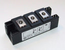
There are some simple ways you can test for failed SCR or Diode using a multimeter and will diagnose 95% of typical device failures. In our example we are looking at a generic 160 Amp Dual Isolated Power Module (MCC162-16io1) from IXYS. The same method can be applied to any type of SCR/Diode in or outside of a Bridge, AC switch circuit, or individually. With reference to the Gate, Cathode and Anode as the relevant pins we will connect to for testing, the pins are the similar for all reputable brands.
SCR simply acts like a Diode when the gate voltage is applied, is it as in its name a Controlled Rectifier. To test the SCR or Diode we need to check for short or open circuit on the Anode to cathode and test for high impedance Anode to Cathode and from Gate to Cathode(SCR's only) which are the main failure modes.


Please set the multimeter to diode/short circuit test and make sure the probes are connected for voltage test. You then test both directions of the Diode/SCR by firmly connecting the positive(red) to Pin 1 and negative(black) probes to Pin 2, and for the second diode connecting the positive(red) to Pin 3 and negative(black) probes to Pin 6.
If the multimeter beeps there is a short circuit and the SCR has failed. If no beep connect the two probes from the multimeter together to ensure the multimeter is functioning properly. Then recheck the pins again from above.
For the diode you will expect to see a voltage of around 0.3-0.7V when testing the forward direction. I.e. Anode (positive-red probe), to Cathode (negative-black probe).
Reverse bias test with Cathode (positive-red probe), to Anode (negative-black probe) should not give a beep. If the multimeter does beep to indicate short circuit, then we can say the diode is failed short circuit.
For SCR you will get no beep for both forward and reverse bias tests.
If there no beep we should further check the restisance to confirm confirm the SCR/Diode has not failed short, or open circuit
As a secondary test we now switch the multimeter to resistance (Ohm) test mode. we then measure the Anode to cathode on both of the devices. You should see hundreds of kOhm to mOhm value. If the impedance is low, in the order of a few thousand kOhms or Ohm then it is a partial failure to short. This can reconfirm the above results or in some cases indicate a partial failure or 'suspect' device as we call them in the industry.
The last test is only for SCR's and is for testing the gate to Cathode on each SCR. Please use resistance test again and check Pin 5 to Pin 2, and Pin 6 to Pin 3. The impedance should be under 10 Ohm or around 10-50 Ohm. If it is very high then the gate is failed or high impedance which will cause firing issue form a drive circuit without adequate drive capability. This failure mode is the most likely failure when the SCR control/firing card has experienced board failure. This can occur due to lightning strikes or transient surges. If this is causing repeated failures we suggest to install a suitable MOV or SPD.
If these tests come up ok, and you are still experiencing issues please contact us and enquire about our in house device testing. We can take it a step further using some specialist test equipment we use in production.
We also sell suitable test equipment as follows.
If you find you device is confirmed failed, we stock a complete range to Diode/SCR Modules, Capsules(PUK), and Stud Mount Devices to suit almost any application.
Feel free to contact us for any further information


