
Fastron - Oztherm Power Controller F311 Series Calibration Procedure
, by Daniel Rehe, 11 min reading time
, by Daniel Rehe, 11 min reading time
In this article we discuss the calibration procedure for F311 Series Single Phase, Phase Angle Thyristor (SCR) Controllers.
In this article we discuss the calibration procedure for F311 Series Single Phase Thyristor (SCR) Controllers.
Please refer to the F311 installation and commissioning manual for detailed wiring connection instructions.
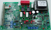
F311 Controllers are fitted with a single PCB marked F321. There should be a silver sticker on the PCB with a serial number in the format of YY-MM-Serial #
There are various options available for this controller which the most common are listed and indicated by the following nomenclature
For detailed descriptions please refer the F311 installation and commissioning manual.
Various "Specials" (SP) versions exist with customised functions and in many cases very minor changes to suit specific customer applications. See here for detailed of most SP versions which have been created to date.
Note: Before beginning please ensure you have at least 200W load connected, can be incandescent light bulbs, or preferably the heating/welding element you intend to use. This ensures that you will have enough load to sink the output. Otherwise it will not be possible to calibrate the controller.
Note: You will need to remove the perspex cover to access the PCB for these procedures.
Note: Leakage of Thyristor (SCR) Semiconductors
Note there will always be some leakage current from the Thyristor (SCR) Semiconductors. Generally, in the the low mA range, or for older devices this can increase as they approach failure, several Amps in the worst cases. What this means is there will always be a voltage present even when the enable of the controller is not connected and the controller is effectively turned off. To prevent leakage in off state you need secondary isolation via contactor or manual isolator to disconnect the circuit fully. This is particularly important when the user needs to enter or touch the heating chamber in between usage.
Set GAIN potentiometer(POT) fully anti-clockwise
Purchase a Current Clamp Meter similar as these Clamp Meters. 300 Amp True RMS Clamp Meter. Or for additional power quality features you can use this 1000 Amp True RMS Clamp Power Meter. We recommend the standard Current Clamp for most applications as it comes with an impedance test functions which is handy to verify failed SCR's or diodes by measuring Anode to Cathode and Gate to Cathode for short circuits or low impedance. See our Diode SCR Testing Blog for the complete test procedure.
Note: Bias Adjustment can be adjusted from -20% to +20%
Connect a 4-20mA signal to terminals 0V (0 volt reference) and I (4-20mA signal input). Input the minimum Control Signal. I.e 0V, 4mA, or 10K POT to 0 position. depending on the input required. Default is 4mA, for 4-20mA input control.
Clamp the active output wire using the current clamp. Adjust the BIAS POT on the PCB control card give the minimum output current to the load. You will know when the controller is at a minimum when the output current will not go down any further.
If you do not have a current clamp available, measure the output voltage to the load and adjust until you have the minimum voltage across the load.
Connect a 4-20mA signal to terminals 0V (0 volt reference) and I (4-20mA signal input). Apply the maximum control signal 10V, 5V, 20mA, or 10K POT position.
Repeat these two steps for a third time to ensure adequate calibration/tuning.
The RAMP potentiometer(POT) sets the step response of the controller for any change in the control input signal. Setting Range in the standard controller is between 1 and 20 seconds. Special versions are available which allow faster turn on for special applications such as spot welding. Check here for list of recorded SP versions made over the last 30+ years. See here for a list of available SP versions.
To check the response time, input a step change to the control input and measure the time taken to reach the desired output.
Note: The Output of the controller will not be sinusoidal when the output is limited. We recommend to only use a True RMS Current Clamp for this procedure
If the output is oscillating while current limit is active, you need to turn the FBG POT fully clockwise, and then gradually turn anticlockwise until the output is stable.
Note: The PW option (Power limit) takes the voltage into account when limiting the output, however with only the C option (Current Limit) it only limits by current. Th reason is due to some applications with small elements or sensitive applications, where there is no temperature feedback loop, as in furnaces for example, as the mains voltage fluctuates, from +10% to -15%, the output power fluctuates. With PW option is measures the voltage and adjusts the input demand signal as necessary.
If the output is oscillating while current limit is active, you need to turn the FBG POT fully clockwise, and then gradually turn anticlockwise until the output is stable.
If you are experiencing nuisance trip, turn the TRIP a further half to one turn clockwise.
On current trip and the controller is disabled and the trip relay energises and latches. Current Trip can be rest by opening the ENABLE link or by turning off the mains supply
Note: Bias Adjustment can be adjusted from -20% to +20%
Apply the maximum control signal 10V, 5V, 20mA, or 10K POT position.
The RAMP potentiometer(POT) sets the step response of the controller for any change in the control input signal. Setting Range in the standard controller is between 1 and 20 seconds. Special versions are available which allow faster turn on for special applications such as spot welding. Check here for list of recorded SP versions made over the last 30+ years. See here for a list of available SP versions.
To check the response time, input a step change to the control input and measure the time taken to reach the desired output.
The standard controller configuration outputs 0-1mA and calibration is performed on the meter side while the output is at maximum and measured using a current, voltage, or power meter
Download this complete procedure in PDF format here
Purchase spare card sets or complete F311 Controllers here


