
Current Transformer (CT) Cable Losses and Accuracy
, by Daniel Rehe, 3 min reading time
, by Daniel Rehe, 3 min reading time
In this blog we discuss the limitations of Current Transformers with respect to maintaining the intended accuracy of a measurement system.
The main limitation we discuss only applies to 1 Amp, or 5 Amp output CT's or coils centers around the term burden, which can also be considered the "load" on the cable or wire used to connect the CT to the meter. The meter itself, the cable and the terminations all add to the burden and therefore must be considered.
For 5 or 1 Amp output CT's, there is a simple and sometimes overlooked rule for selecting and sizing CT's and CT cable. The rule is as follows.
The burden shall not exceed the maximum specifications of the CT in order to maintain accuracy in the measurement system.
The simple formula is
CT Burden ≥ VA(Burden) of Meter + VA(Burden) CT Cable + VA(Burden of Terminations)
If we assume the termination burden is negligible then we should take one example and refer to the following table.
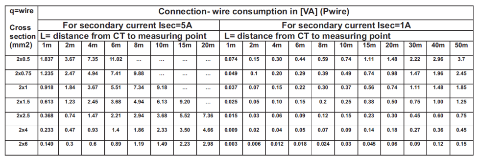
We plan to use a 5 Amp CT or Meter with 0.5mm² diameter core wire and we wish to run 2M length to the meter. Our meter (in this case Cube 400 by Northern Design) has a burden of 0.1VA, and the cable has a burden of 3.67VA. Therefore our total burden is 0.1VA + 3.67VA = 3.77VA.
This means we need to select a CT with at least 3.8 or 4 VA
In practice there maybe be some nominal losses associated with the terminations, so if you are extending cables through additional terminations then you need to consider the additional burden or losses introduced.
In this situation you have at least three possible options;
The second and third option might not be possible in retrofit apllications. if you need any further advice or clarifications on what CT's are available, feel free to contact us so we can confirm with any of our numerous CT suppliers.
0.333V output types usually found with USA based equipment such as Solar Edge, or also for inverters such as Fronius specify the maximum wire length acceptable for connection to the system. In many cases the wire is provided or hard wired into the Current Sensor.
As a general rule, avoid extending cable where possible. Do not run CT cable longer than 10 Meters, and use shielded cable as the voltage signal is highly sensitive to external electrical noise.
Rogowski Coils typically have a very low burden on the meter side of the integrator, which gives limitations for where the integrator is located. However the coils side connection from the coils to the integrator can have the cable length extended in many cases up to 1000 Meters. by extending the cable length some minor phase shift is introduced due the wire capacitance. This phase error should be considered for long cable runs. Within 50M we can say there is no dramatic effect which will cause less than class 1 accuracy for the coil and integrator combined.
For further detail, feel free to contact the friendly sales team as Fastron electronics
how long is length of the cable from current transformer to input of controller ? Can the connection distance be 300 met? Can you send me the document?


