Basic Wiring Instructions for FRI 8 series Current Switches
In this blog we run through the basic wiring diagram for FRI 8 series Current Switches
A1) For Direct Connection without External CT
Here were are referring to Model FRI8-01/XX, FRI8-01/XX, FRI8-01/XX, and FRI8-01/XX which are available in ratings 0.05 to 0.5 Amp, 0.1 to 1 Amp, 0.5 to 5 Amp, 0.8 to 8 Amp and 1.6 to 16 Amp Ranges.
See our added details to the FRI 8 series wiring diagram below.

1) The red L and N are the power supply connections. Note: if not using 230/240VAC this can be 24VAC or 24VDC and is not polarity sensitive.
2) The  symbol is the load device.
3) Connect L to B1 and then connect B2 to the load. The other side of the load goes to N.
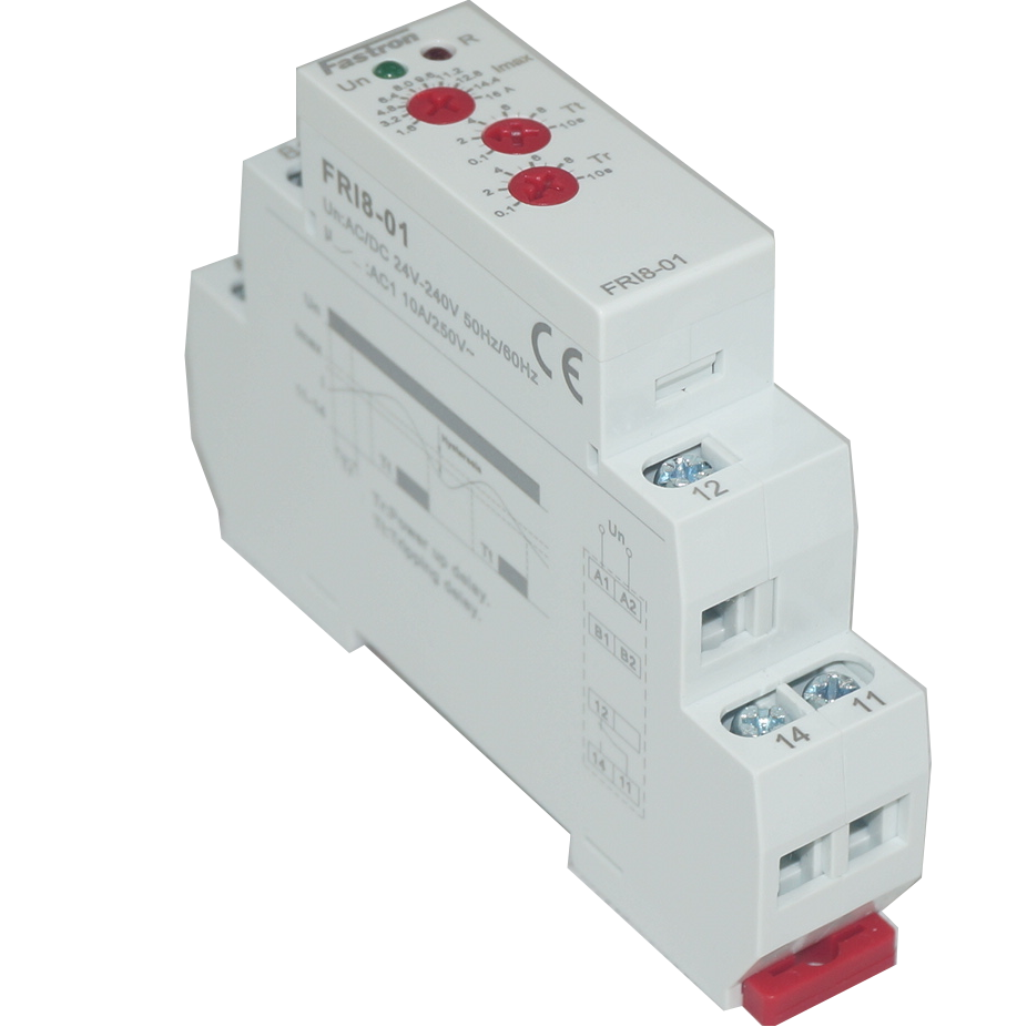
4) Relay terminals 11 and 12 normally closed, and 11 and 14 are normally open relay outputs.
A2) For Connection via External CT
See our added details to the FRI 8 series wiring diagram below.
1) The red L and N are the power supply connections. Note: if not using 230/240VAC this can be 24VAC or 24VDC and is not polarity sensitive.
2) The symbol is the load device.
3) Connect S1 of CT secondary to B1 and then connect S2 of CT secondary to the load. Then Clip the CT over the the conductor which is carrying current to the load.
Please Note: A 5 Amp or 1 Amp secondary CT is recommended. And you will use FRI8-01/1 (0.1 to 1 Amp) or FRI8-01/5 (0.5 to 5 Amp) Current switch. if the measurement current is very low then we suggest to use FRI8-01/0.5 (0.05 to 0.5) Amp Current switch
4) Relay terminals 11 and 12 normally closed, and 11 and 14 are normally open relay outputs.
B) For FRI8 Series with integrated CT or Hall Sensor
Here we refer to models FRI 8-01/A, FRI8-01/B, FRI 8-06/A, FRI8-06/B
See our added details to the FRI 8 series wiring diagram below.

1) The red L and N are the power supply connections. Note: if not using 230/240VAC this can be 24VAC or 24VDC and is not polarity sensitive.
2) The symbol is the load device.
3A) If not used additional external CT, simply run the load wire through the aperture of the integrated Current sensor

3B) If using additional External CT, simply Run one of the CT secondary wired through the integrated current sensor aperture on FRI8 and then terminal the CT on itself.
Please Note: a 5 Amp secondary CT is recommended for the best accuracy
4) Relay terminals 11 and 12 normally closed, and 11 and 14 are normally open relay outputs.
5) If you wish to use as an undercurrent relay, then you can link Y1 and Y2
For further questions, please contact our friendly sales team at Fastron Electronics
, DIN Rail Mount kWh Meter, Single Phase, 240VAC aux, Class 1, 100Amp Direct Connect, w/ 2 x pulse outputs and RS485 Modbus RTU Comms, MID Approved,SAA212516")