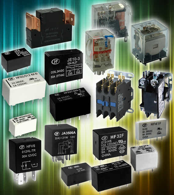
General Applications for Relays and Contactors
General Applications for Relays and Contactors
Solid State Relays
Solid State Relays (SSRs) are semiconductor based switches used to switch current loads via an isolated electronic circuit. Galvanic separation is achieved via an optoelectronic element such as a IR emitting diode , a phototransistor, diode, phphotothyristor or phototriac. In the 'off state', when no current flows through the input circuit, the optoelectronic element remains switched off and the Solid State Relays output resistance is very large. After activating the diode, the photoelement is irradiated and the switching load starts to conduct. This technology significantly increases the switching frequency, and eliminates the phenomenon of electric arc. Typicallly the Solid State Relay can last for 109. Which is a 1000 fold increase from meachanical relays and/or contactors
Block diagram of a Solid State Relay
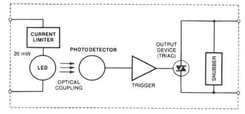
Depending on the Solid State Relay type, the device may be switched on by supplying a DC input voltage (from 3/4V to 32V) or an AC voltage (from 90V to 280V at 50Hz) to the input terminals. Depending on the application, they can switch DC and AC currents. There are also three-phase Solid State Relays used, for example, for switching three-phase electric motors, or heater banks.
Types and application:
|
 |
|
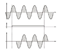
Random Crossing Relays switching on "instantly" - Switching takes place instantly after applying the control voltage.
This type of control is intended for solutions where a short response time is required. |
 |
|
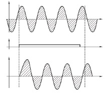
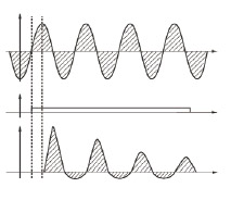
Relays switching on the voltage at the "peak" - Solid State Relay is activated when the peak power supply voltage is reached.
Used for strongly inductive loads (transformers). |
 |
|
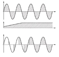
Proprtional control relays - Controlled by an analog demand signal (2-10V DC or 4-20mA DC).
Used for Phase or Burst control of light intensity, heating, etc. |
 |
Parameters characterizing Solid State Relays:
Input circuit:
- Control voltage range - voltage range supplied to the input, in which the relay remains switched on (eg: 3-32VDC, 9-280VAC),
- input current range - determines the maximum input current for the relay on and off state,
- switch-on and switch-off time - time elapsed since the control signal is supplied / disconnected to the full enable/disable of the relay.
Output circuit:
- load voltage range - voltage range supplied to the output terminals,
- maximum voltage - maximum permissible value of overvoltage in the power supply network that does not damage the relay,
- load current - maximum permissible value of current flowing in the output circuit,
- maximum unique overload current - maximum value of the current pulse with the duration of one half of the sinusoid,
- maximum I2 t - Joula integral value, used in the selection of fuses.
Useful parameters:
- insulation voltage – effective value of the mains voltage which can occur between the input and output terminals of the relay,
- insulation resistance – the minimum value of the resistance measured using a 500V constant current signal,
- capacity between input and output – measured between input and output terminals,
- ambient temperature range during operation.
Relay Cooling
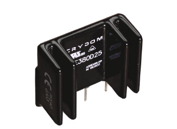
The lifetime of Solid State Relay is virtually unlimited, provided that they are properly cooled. Therefore, special attention should be paid to the selection of the heat sink, use thermal grease and ensure adequate air circulation. A good solution is to mount the relay with a heat sink on the DIN rail, leaving around free space.
Relay Protection
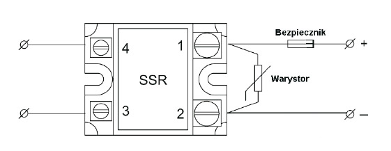
Another important thing is protection against the effects of a short circuit or overload. Time-saving fuses can not protect Solid State Relays, therefore, for proper protection, ultra-fast fuses should be used, whose Joule integral is smaller than the value of the semiconductor integral. For full protection of the relay, a varistor for overvoltage protection should be connected at the output.
Electromechanical relays
The principle of operation of electromagnetic relays is similar to the principle of operation of an electromagnetic contactor. The relay contacts have a relatively low load capacity, in the order of a few amperes. Therefore, the relay is equipped with a much smaller electromagnet than the contactor, and the contacts do not have additional arc supression devices.
The relay's dimensions are smaller than the contactor's dimensions, while the relay's durability is very high and reaches several dozen million connections. Depending on the purpose, relays have one or more pairs of contacts. They can operate under the influence of changes in current, voltage, direction of current flow, frequency, phase shift, etc. The principle of the relay operation is explained in the figure:
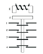
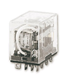
The flow of current through the coil winding causes the attraction of the armature. When the armature is pulled, the contacts close: (1), (2), (3) and open break contacts (4). After disconnecting the voltage and dropping the armature, the following contacts open: (1), (2), (3) and close the break contact (4). In the most common construction solutions of relays, the coil voltage is 230VAC or 24VDC, operating current of contacts - from 1 to 10A, the number of contacts - from one to four switching pairs.
Contactors
The contactor is a switch whose operating contacts are closed by means of an electromagnet and kept in this state until the coil voltage is high enough. After breaking the circuit of the electromagnet coil, the armature falls (under the influence of the spring) and the working contacts open.
The construction and operation of contactors are similar to the construction and operation of electromagnetic relays. The difference is that contactors are used to connect main circuits (e.g. motors), while electromagnetic relays have the task of connecting auxiliary circuits (e.g. control, signaling). In addition to the main contacts, the contactors may have several auxiliary contacts for signaling or blocking. The principle of the contactor operation is explained in the figure:
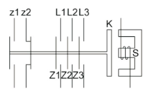

Under the influence of the current flowing through the contactor S coil, a force is created that attracts the armature K, which causes shorting of the main contacts Z1, Z2, Z3 and auxiliary contacts z1, z2.
The contactors are mainly designed for remote connection of three-phase AC circuits in conditions specified by the use category AC3 and AC4 (connection of squirrel-cage motors). They can also be used to connect ring motors (category AC2) or heating devices (category AC1).
In addition to AC contactors, DC contactors are also available. They have an electromagnet or pneumatic drive, with both electromagnets and solenoid valves controlled by direct current. The main applications of these contactors are rail, tram and battery traction (trolleys).

