
Setting up PCB1 Pattern Controller Program
, by Anita Eerdekens, 3 min reading time
, by Anita Eerdekens, 3 min reading time
In this blog article we walk you through setting up a Shinko PCB1 Series Temperature Controller for Ramp and Soak operation also referred to as step control sequence setting. In this programming guide, our customer would like to ramp up as quickly as possible to 70 Deg C.
In this Blog article we show you the steps for setting up PCB1 Pattern Controller Program
In this blog article we walk you through setting up a Shinko PCB1 Series Temperature Controller for Ramp and Soak operation also referred to as step control sequence setting.
In this programming guide, our customer would like to ramp up as quickly as possible to 70 Deg C.
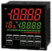
1. First step is to check the input sensor is set to the correct type. Power up the controller and you will see the PV/SV Display. Access the Initial setting mode as shown below.

Press up/down keys to set to Pt100 for RTD Pt100 with Deg C display which can be with decimal point or without decimal point.

2. Set the Program Start Type to SV Start
If you prefer you can set the program start temperature to PV to start at room temperature.
Now press the circle(mode) key until you get back to the PV/SV display screen. Or you can wait 1 minute it will revert.
3.Setting the Step Program Sequence
The full example of setting the steps and times is on pages 91-94 of the attached manual.
For the actual setup of the step times and temperatures, we have the following menu

4. You need to set SV1 to 80 Deg C
Then set Step time 1 minute, to the time in seconds you wish to ramp up the temperature.
5. Set the SV2 to 80 Deg C
Then set the SV2 step time to 5 minutes.
For ramp down you can either leave the program to stop after the time is up, or
If you want a controlled cool down, you can set SV3 to Ambient temp or lower.
Then set the Step time 3 to the time you wish the controller to gradually ramp down to SV3 temperature setting.
6. Wait Function Setting. In order to make sure the Step reaches the desired Temp you can enter a wait value in Deg C which will thn make sure the controller reaches within the wait value. For example a wait value of 1 will make the controller hold the step until it reaches within 1 Deg C then will advance regardless of the step time setting. Thsi is useful in hot/cold climates with little or no insulation in the heating chamber and the required temperature is critical.

You can set a single wait value for all steps. You can also disable the wait function completely using the above menu.
The wait value is used for if you set the timing too short, for example if in the cooler months it takes longer than X seconds to heat up then the controller will not go to the next step until the temperature minus the wait value is reached. So if you do want the controller to wait,best to have it set at 1 or a few degrees depending on the application.
7. To start the Program (RUN) you need to go back to the main display by either waiting for 1 minute, or pressing the mode key until you see the PV temperature display. Once there simply press the RUN key and the SV display will start counting from 0 for SV start, or from the PV value for PV start.
The controller counts up to SV1 (80 Deg C) in the time set in SV1 time. Then will hold at 80 Deg C for 5 minutes.
Finally the controller will turn the output off after total 6 minutes of operation.
Note for DC current or voltage inputs, the wait function is 0-20% of input value instead of Deg C.
I hope this helped you. If still stuck you can email us anytime at sales@fastron.com.au.


