
Setting up Electronicon PFR / Beluk PFC-CX / Vishay Estamat PFC-12N Power Factor Controllers
, by Daniel Rehe, 2 min reading time
, by Daniel Rehe, 2 min reading time
Setting up Electronicon PFR / Beluk PFC-CX / Vishay Estamat PFC-12N Power Factor Controllers
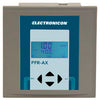
In this blog we will run through the basic setup of Electronicon PFR-X-R Power Factor Controller. Also sold as / Beluk PFC-CX / Vishay Estamat PFC-12N
The Full User Manual can be downloaded below which covers all three brands of re-badged controllers.
For our example We have a power factor system with 4 x 50 kvar steps and 2 x 25kvar steps.
For 50kvar @ 400VAC step, we have 2 x 40kvar @ 525V in parallel
For 25 kvar @ 400VAC step, we have 1 x 40kvar @ 525V
With the mains and auxiliary power switched off, connect to the PFC system as below. Note 1 Amp or 5 Amp Current Transformer can be used. Current Transformer should be chosen to allow for the maximum current which can be seen. In our case we use the maximum current value @ 440VAC which is 36.9 Amp per capacitor. Total will be 36.9 x 10 = 369 Amp. so we suggest 400/5 CT ratio.
Note: Refer to Page 4 of user manual for step by step safety guide.

Note: For 400VAC systems there is not need to change the voltage Un setting.
Once powered up and connected correctly you will see a COS Ø number showing the state of the Power factor on site.
2A)To Set Nominal Voltage, CT Ratio, Target PF, and Switch Interval etc access the menu below.

2B) If using a different voltage than 400V then change UN to the new voltage.
- For 400/5 CT set "ct" value to 80
2C) if using Primary (or step down) Transformer you can se the VT ratio in parameter "vt". leave it as "1" for not PT
2D) Set "ai" to YES (for auto Capacitor initialisation which detects the kvar ratings)
2E) Set "pfc" to "ON" for automatic control. Note: if need to stop control. access thsi menu and set to "O FF"
2F) Set "cpi" to 0.95 for target Power factor of 0.95
2G) Set "st" to "120" to limit the contactor to switch no faster than 2 minute (120 second) intervals
2H) Set "out" to AUTO to allow for the controller to regulate power factor
For full details on the range of parameter setting, please see page 16 of the Electronicon PFR-X user manual
Once completed above the PFR controller should run through the auto test feature then start correcting after completed. the test procedure turns on each step to detect the correction kvar values.
If you are getting over correction of COS Ø, and all settings are correct, then you may need to set the steps manually. See page 35 of the user manual and follow the manual setup instructions.
For further questions, please contact our friendly sales team at Fastron Electronics


