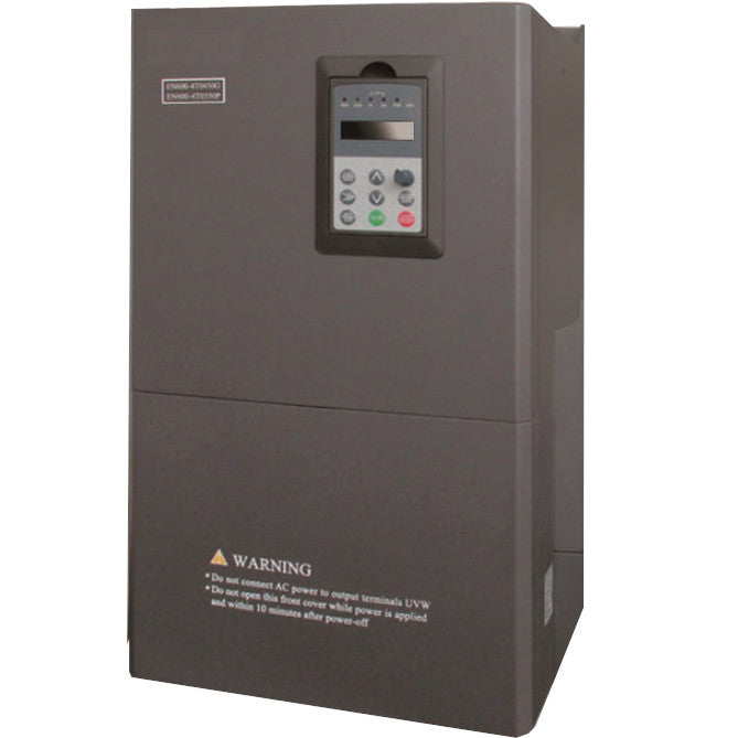
Setting up Motor Control for Fastron EN600/EN500 Series Variable Speed Drives (Variable Frequency Drives)
In this blog we discuss seting up Fastron EN600/EN500 VSD (Vraiable Frequency Drive) for Manual and Automatic Motor control of Induction Motors
A. Scope of VSD Control Panel
B. Basic Operation of VSD Keypad
C. Setup of VSD to Motor Name Plate
D. Setup of VSD I/O and operation for VSD Control Panel
E. Basic Operation of VSD Control Panel
F. Indicator Outputs from VSD
G. RESET of Faults
H. Physical Connections to terminals on VSD
Appendix 1 & 2 VSD and PLC Internal Wiring

A. Scope of VSD Control Panel
Machine is jamming regularly. PLC program and VSD to automatically reverse and retry to avoid further blockage.
1.Soft start forward (5 second soft start)
2.When shredder starts to stall out under load (on pre-jam detected for 140Amp, now pause reverse and forward again)
3.VSD to reverse for 6 seconds
4.Pause 4 seconds
5.Then re start forward (soft start).
We chose ENC Variable Speed Drive top achieve the result, on blockage 140A pause reverse and forward again for 5 attempts, after which the VSD will remain in fault E-10 which is Over Current Arrived (detected).
We consider the above automatic control. For safety and fallback, we will also implement Manual control with FWD, REV, REV JOG (15Hz) modes. This will require PLC program to be stopped by auto/manual toggle switch.
B. Basic Operation of VSD Keypad
To configure the VSD to interface with external PLC Control Panel
Note: To access the settings of function codes, simply press the menu button and use the right double arrow and the Dial to scroll through the function code numbers. Press ENT button to make selection or save the settings. Press enter again to check the configured parameter for any Function code Fxx to Fxx
C. Setup of VSD to Motor Name Plate
C1 For 50Hz Motor, set F01.11=50
C2 Set Functions codes F15.01 through to F15.04 to the relevant motor parameters kW, Voltage, Rated Motor Current, Rated Frequency
D. Setup of VSD I/O and operation for VSD Control Panel
D1 First we need to set the 3 wire control mode:
Set Function Code F08.26 = 30
D2 Second we need to set Run command channel selection:
Set Function Code F01.15=1
D3 For external Control by PLC or other, we need to assign the digital inputs X1,X2,X3,X4.
D4 For X1 input we set to Forward Running Command (Normally Open)
->Set F08.18 to 01
D5 For X2 input we set to Reverse Running Command (Normally Open)
->Set F08.19 to 02
D6 For X3 input we set to Reverse Jogging Action Command with default 5Hz output (Normally Open)
->Set F08.20 to 04 (5Hz is default, if need different Hz set F01.26 0 to 6000 in 0.1Hz increments)
D7 For X4 input we set to 3 Wire Running Control (Normally Closed, Open to stop)
->Set F08.21 to 30
D8 For X5 Input we set to External Resetting Input which will reset any alarm or faults (Normally Open)
->Set F08.22 to 24
For Normally Open inputs, the contact needs to be closed for action. For Normally Closed 3 wire running mode, if the terminals are opened the running will stop until closed again and one of the action buttons is pressed again.
As a precaution for unloaded motors, we will set a dead time of 3 seconds to prevent reverse or forward.
D9 Set F2.20 to 3.0 for 3 seconds delay for forward/reverse
D10) Setting Soft start forward → See “Acceleration Time” Function Code F01.17
To set soft start, access Set Function Code F01.17 and set to the soft start period in 0.1 second increments increments. Range is 1 to 6000 (0.1 to 600 seconds)
For our case, set to 50 (5 seconds)
D11 Setting Deceleration time. → Set Function Code F01.18 and set to the soft start period in 0.1 second increments increments. Range is 1 to 6000 (0.1 to 600 seconds)
For our case, set to 10 (1 second)
D12 When shredder starts to stall out under load. (140 Amp internal detection)
Please Note: ENC VSD can set over current detection from 0 to 250% of rated current. In this case 66.6% is ~140 Amp
To set over current detection alarm, set F09.00 = 8. (Over current arrived)
Then set F09.14 to 66.6 (66.6% of nominal current rating)
From EN600 VSD on blockage detected at 140A Load, then pause, reverse 6 seconds and forward again.
E) Basic Operation of VSD Control Panel
Manual Operation Mode:
Button allows the user to manually adjust the motor via:
AUTO MAN → set to MAN for Manual operation
Forward RUN → Momentary press to turn on, stop to turn off
Reverse RUN → Momentary press to turn on, stop to turn off
Reverse JOG → Momentary press to pulse the motor to reverse (useful for safety)
RESET → To reset faults./alarms
STOP → To stop motor running.
Motor running GREEN LED →will turn on for any motor movement,. Forward, reverse, or jog.
Reset LED →will turn on when WHITE reset button is pressed
Fault LED →will turn on if motor if VSD shows fault to PLC
Automatic Operation Mode:
AUTO MAN → set to AUTO for Automatic operation
FORWARD RUN → Will start PLC /Motor Running Program
STOP → Will stop Motor running
RESET → Will reset any VSD or PLC faults
Motor running GREEN LED →Will turn on for any motor movement. Forward or reverse
Reset LED →Will turn on at program start and turn after RESET
Fault LED →Will turn on i f over current condition has been detected 5 times in a row

F) Indicator Outputs:
F1 Set Y1 to operation run output (F09.00 = 1) and switch 24VDC into Green RUN button
F2) Set Y2 to over current (F09.01 = 8) and connect to WHITE 24VDC indicator
F3) Set Y3 to Alarm (F09.02 = 22) and connect to AMBER 24VDC Alarm indicator
F4) Set Y4 to Fault (F09.03 = 23)and connect to RED 24VDC FAULT indicator
G) Reset of Faults/Alarms
-Reset faults by shorting X5 terminal to COM terminal
Note : Factory reset of PLC: Set Function Code F00.14=510

IMPORTANT NOTE: X COM on terminal strip is connected to +24V terminal on VSD
This is because the VSD uses Transistor outputs to Indicators which will switch 0V to our interface relays. Also we use High Level Valid I/O on the inputs to the VSD.
If you need further support, please contact the friendly sales team at Fastron Electronics

