Heat Sink Selection for Solid state Relays
Heat Sink Selection for Solid state Relays. How to select the correct heatsink.
We are constantly asked and surpised that many peopel di not understand how to select a basic heatsink for the application
The SSR may do more than 60 Amp in fact... the 60 Amp rating is applicable only with suitable heat sink to dissipate the heat.
For example, for 35 Amp load, the heat dissipation will be 35 x 1.5 x 3 = 157.5 Watts in heat
Heat sink thermal impedance is measured in deg C/Watt.
Take ambient temp maximum of 40 Deg C + the heat rise.
Heat sink is selected to make sure the heat sink stays below or around 100 Deg C maximum, (at the base of device). This is equivalent to 60 Deg C rise in temperature, if the maximum ambient temperature where the SSR is located will be 40 Deg C.
So if we take 157.5 watts and multiply by the heat sink impedance, this result must be below 60 . I.e. 157.5W x HS = 60
Or 60 = 157.5 = 0.38 Deg C per watt minimum, where the lower figure if better
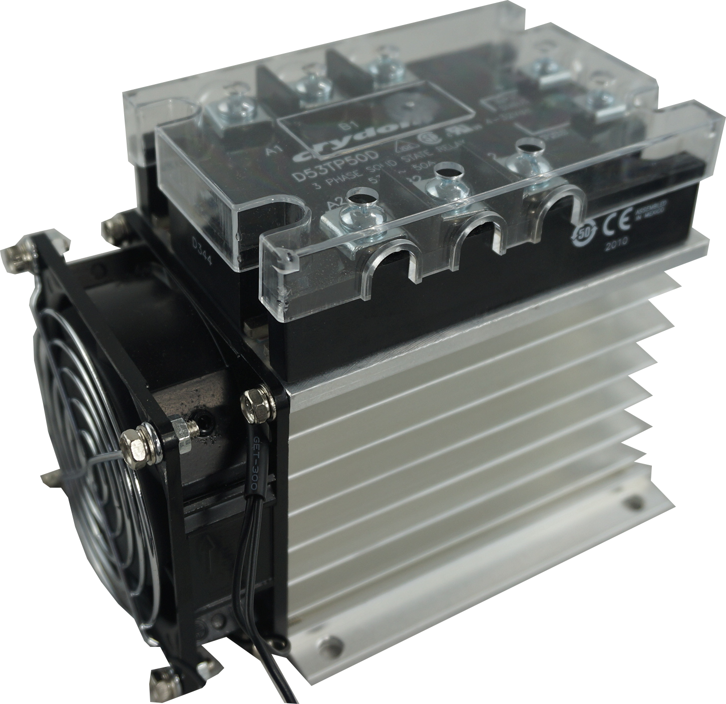
Therefore we recommend; HS212F(Panel Mount) or HS212DR-F (DIN Rail mount) Both with fan
We do offer non fan cooled option however as you can see with below you are only able to get 34 Amp output. This may be why the SSR was failing before.
In addition you should be sure to check the SSR data sheet curves to ensure the SSR itself is adequately rated . See example for D53TP50D curves below.

For further information feel free to contact the friendly sales team at Fastron Electronics
, DIN Rail Mount kWh Meter, Single Phase, 240VAC aux, Class 1, 100Amp Direct Connect, w/ 2 x pulse outputs and RS485 Modbus RTU Comms, MID Approved,SAA212516")