How to test a Hall Effect Sensor is Damaged?
In complex control systems you may have the requirement from time to time to check if the Hall Effect Sensor is working correctly.
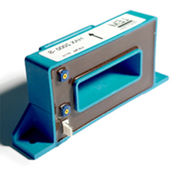
In this example we will use a typical LEM sensor which gives +/-4V output for nominal 1500 Amp DC input. For these type of sensors you will require a bipolar supply or two isolated power supplies connected as shown.
Wiring of a typical +/-4V Hall Effect sensor

1) No Load Test
First step is to power up the sensor with no live measurement conductor inserted. If the sensor is still installed in busbar or cable, please make sure the conductor is not live.
Connect as shown above using the correct power supply voltage. Note most LEM sensors use +/-15VDC or higher voltages. In our case we use HAX 1500-S and +/-15VDC is suitable.
Connect a multimeter to 0V and M output. The output should be close to 0V (a brand new sensor may be around 40-50mV based on 1% error on 4V . You will only see the bottom end noise in that case.
If the output is much higher like 0.5V -4V or even higher than we can say the sensor needs to be replaced.
Note the normal life time of these sensor is 10-15 years on service. However if they are subjected to high overloads, or small overloads for a prolonged period, then the DC offset error will increase and eventually you lose the measurement range of the sensors. In extreme cases if the output is above 0.5V and the sensor is now damaged and cponsidered unusable. This can depend oin the control systems ability to adjiust out the DC offset in some way.
1) Load Test
If there is nor high offset in the sensor output, then we need to try a live load test.
Make sure the sensor is safely installed on the busbar, or in a test lab environment you can run multiple turns though the CT as shown.
Try to test at least 50% of the range, so for 1500 Amp range, you could to run 15 Amp wire through the CT for 100 turns, or 50 turns for 750 Amp

If you can see a linear reltionship on the input vs output for the complete range, then the sensor is working as intended.
If you have further questions feel free to reach out to our friendly team at Fastron Electronics
, DIN Rail Mount kWh Meter, Single Phase, 240VAC aux, Class 1, 100Amp Direct Connect, w/ 2 x pulse outputs and RS485 Modbus RTU Comms, MID Approved,SAA212516")