A Move Into Miniaturization for Current Sensing in Power Conversion Systems
A Move Into Miniaturization for Current Sensing in Power Conversion Systems
Written By:Steve Bottari – LEM USA Regional Product Manager - Smart Grid
Modern power conversion systems must simultaneously become more efficient, smaller and cheaper than the previous generation. With this in mind, LEM, the global leader in current and voltage sensing, has used its industrial expertise to create a single chip package: the HMSR current sensor.
Introduction
The traditional way to measure current is to use open-loop Hall effect sensors. The magnetic field created by a current is captured by a magnetic core and measured by a Hall element. More recently, dedicated ASICs helped to increase the overall accuracy of the system using advanced compensation techniques.

Figure 1:Open-loop technology principle using a traditional Hall effect chip or a dedicated ASIC

Figure 2:Evolution of LEM’s
current sensor size over the decades LEM first moved into miniaturization with the LTSR product in the previous decade. At that time, the best way to ensure optimum performance was to use closed-loop Hall effect technology in combination with a special closedloop ASIC designed by LEM. The evolution of ASIC technology enabled the development of open-loop Hall effect sensors capable of approaching the performance levels delivered by closed-loop technology. Not only did open-loop technology make it easier to reduce the size of components, but it also met market demands with lowered costs, thanks to a simplified structure and reduced power consumption. The current decade has seen the development of the HLSR series, which not only delivers high performance in terms of offset and drift, but also excellent response time – and all in a package small enough for PCBA-type applications.
LEM has developed and applied extensive knowledge and design expertise over many years to create the HMSR, a state-of-the-art current sensor that satisfies the continuous market requirements of cost reduction, performance improvements and miniaturization.
With this new series, LEM is expanding its miniature current sensors range for isolated AC and DC current measurement. The new HMSR models are easy to use because they include a low-resistance primary conductor (which minimizes power losses), a miniature ferrite, and a proprietary ASIC to allow direct current measurement and consistent insulation performance.
HMSR Current Sensors
This new product category already includes six different nominal currents – 6A, 8A, 10A, 15A, 20A and 30A – with a measurement span 2.5 times the nominal current available in a footprint package similar to SOIC-16. Standard models provide an analog voltage output with different sensitivity levels available, and 5V power supply versions achieve an output voltage of 800 mV at IPN.

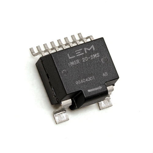
Figure 3:HMSR current sensor Two overcurrent detection units (OCD) are built in to separate the control application path from the safety loop. These OCDs are on two dedicated pins – one set internally at 2.93 x IPN as threshold, and one externally that offers threshold adjustment capabilities to users.
However, HMSR sensors should not be seen as simple open-loop Hall effect ASIC-based transducers. The HMSR’s unique primary conductor allows overload punctual currents and a high level of insulation. All this is combined with a ferrite-based magnetic circuit to provide excellent immunity against the external inhomogeneous fields found in power electronics applications. This enables the HMSR to be used in environments with high levels of disturbance.
The ferrite used in the HMSR is also a key factor in achieving a high-frequency bandwidth of 270 kHz (3 dB) and makes it possible to achieve good rejection against external fields.
These dedicated ASIC designs combine field-proven techniques such as spinning, programmable internal temperature compensation (EEPROM) for improved gain, and offset drifts. The result is high levels of accuracy across a range of temperatures (-40°C to +125°C) with a typical value of 0.5 % of IPN (HMSR 20-SMS model). Power conversion applications such as solar inverters or drives demand high efficiency levels and can only be reached if the control loop is accurate.
Compared to the previous generation of products, the HMSR has greatly improved accuracy over temperature figures. The graph below shows the low level of typical overall error across a measured current with the HMSR 20-SMS, as well as exceptional linearity on a wide temperature range (-40°C to +125°C).

Figure 4:Typical overall accuracy and linearity for HMSR 20-SMS model from -40°C to +125°C

Figure 5:Response time for HMSR 30-SMS
Such accuracy is not enough if it isn’t backed by a fast response time. To this end, the deployment of a fast IGBT (similar to SiC-based technology) increases the possibility of working with a faster switching frequency. The HMSR is proven to be ready for such demands
below 2 µS (Figure 5).

Figure 6:HMSR mounted with IPM
5. Benefits of HMSR
In multiple applications, HMSR sensors can be mounted directly onto a printed circuit board as SOIC-16 SMD devices, reducing manufacturing costs and footprint requirements in restricted environments. Measuring just 6mm in height, the HMSR offers significant space savings, making it a preferred option over intelligent power modules (IPM) under the heatsink (Figure 6).
Figure 7:Maximum Power Point
Another area where the HMSR will deliver significant benefits in terms of current measurement is in solar applications. In particular, the maximum power point tracker (MPPT), an important asset in solar energy conversion, is a collection of components that maximize the power generated from a photovoltaic (PV) panel. It does this by regulating current and voltage depending on temperature, sunshine and total resistance of the system. The control system permanently analyzes system output after injecting a small perturbation (using the perturb and observe method). The MPPT then analyzes the resulting power by sensing voltage and current, and deducts the parameter to change in order to reach the maximum power point (MPP). The MPPT then adjusts the pulse width modulation (PWM) to adapt the voltage of the DC/DC converter.
Figure 8:MPPT architecture

The greater the accuracy and lower the noise, the better MPPT performance will be. Using LEM’s state-of-the art ASIC, the HMSR provides a highly accurate and very low noise signal, which allows the system to operate at optimal levels.
String current monitoring also makes it possible to compare several strings for detecting issues such as faulty wiring, dirt on the panels, and shadows created by growing trees. In addition, the DC/DC converter used in the MPPT uses high-frequency regulation, around 80kHz, to create high dv/dt, which is harmful for electronic components. Thanks to its ruggedized design, the HMSR offers significant resistance to noisy environments.
This immunity can easily be checked by applying dv/dt through the sensor and observing the output reaction. The following graph shows the low disturbance created by applying dv/dt through the sensor. The error generated is only 3% of full scale with a recovery time of 3.8 µS (Figure 9).
The two available built-in OCDs on the HMSR will also protect transistors on the inverter from short-circuiting and overload. This kind of detection and protection is an important feature for multiple applications, such as HVAC on the DC link or motor drives. Most modern variable-frequency drives (VFD) incorporate a motor overload algorithm, and the OCD function on the HMSR will make detection much easier, preventing the overheating of equipment. Having two distinct OCDs provides the opportunity to monitor overload and short-circuit events separately.
Of course, when it comes to choosing a current sensor, isolation requirements could be an issue for the adoption of IC packages. For example, in the solar industry, power plants are often used with higher DC voltages (up to 1500V) in order to increase the DC/AC power ratios. This dramatically increases the isolation needed for a current converter.
HMSR 20-SMS tested with pulsed voltage of +/- 1000 V at 20kV/µS:
Figure 9:Error generated at the HMSR output after applying dv/dt

The long internal distance between primary and secondary sides helps to isolate the primary bar with the rest of the IC, giving a very high level of isolation guaranteed at 4.95 kVRMS (at an AC insulation test voltage of 50 Hz, 1 min). This level will be guaranteed for 100% of shipped products tested during production assembly. The special footprint of the HMSR allows 8mm creepage and clearance distances on the landing pad.
A higher comparative tracking index (CTI) means a lower minimum creepage distance is needed with a CTI of > 600. According to the IEC 62109-1 (Safety of power converters for use in photovoltaic power systems), the working voltage for the HMSR reaches 1600V, which means it is ideally suited for high-constraint applications.
Another key requirement in the solar industry is that equipment needs to be surge tolerant up to 20 kA to offer effective lightning protection. With the HMSR placed directly on to the string inputs that are subject to lightning, components will be extremely robust against such powerful current surges. The HMSR has been designed and tested to this level according to the standard 8/20 µS surge test profile (Figure 10).

Figure 10:Typical overcurrent surge profile in solar applications

Figure 11:HMSR demo-board
LEM has developed an HMSR evaluation board that makes it possible to prototype and quickly test the extraordinary performances of this new generation of sensors. Available as a sample on request, this new product line will enter mass production in early 2020 (Figure 11). available for sampling

Leading the world in electrical measurement,
LEM engineers the best solutions in energy and mobility, ensuring that customers’ solutions are optimized, reliable and safe. Its core products - current and voltage transducers - are used in a broad range of applications in drives & welding, renewable energies & power supplies, traction, high precision, conventional, and green car businesses. LEM is a mid-size, global company with production plants in Geneva (Switzerland), Sofia (Bulgaria),
Beijing (China) and Machida (Japan).
With its regional sales offices close to its clients’ locations, the company offers seamless service around the globe.
LEM USA Central, Alan Garcia LEM USA East, Greg Parker
LEM USA Midwest, David Hanley LEM USA, Inc. Central Office, 11665 West Bradley Road, Milwaukee, WI 53224, USA Toll free: 800 236 5366 | Tel: +1 414 353 0711 | Fax: +1 414 353 0733 | Email: lus@lem.com
LEM USA West, Stephen Bottari
w w w. l e m . c o m
For PDF Copy please go here
, DIN Rail Mount kWh Meter, Single Phase, 240VAC aux, Class 1, 100Amp Direct Connect, w/ 2 x pulse outputs and RS485 Modbus RTU Comms, MID Approved,SAA212516")