MS Power MSD151R18UB, Rectifier Diode 150 Amp, 1800V, 1/2"20UNF, Anode stud
Features
Full blocking capability over wide temperature range
Hermetic metal case with glass insulator
Threaded stud
Applications
Power Supplies
Uncontrolled Rectifiers
Oil Cooled Circuits
Battery Chargers
Specification
MS Power Part Number
MSD151R18UB
Vrrm
1800V
Diode Configuration
Anode Stud
IF(av) @ 100 Deg C
165 Amp
IF(av) @ 125 Deg C
130 Amp
Itsm
2.5 kA
VF(to)
0.85V
Tj(max)
180°C
rF
1.3mΩ
Termination Style (Tail)
10mm Round Lug
Termination Style (Stud)
1/2" 20UNF 2A
Tail Length to Stud
185mm
R th(j-c)
0.28°C/W
R th(c-h)
0.05°C/W
Weight
110g
Mounting Torque
10 - 13 Nm
Factory Pack Qty
10
Country Of Origin
China
MS Power Headquarters
Germany
Datasheet
Product Datasheet
Infineon TT104N16KOF Dual Thyristor Module
Features
Pressure Contact Technology
Optimised for Deep Cycling
Electrically insulated base plate
Very low forward voltage drop
Very low leakage current
3600V Isolation
Industrial standard package
20mm Base Width
Applications
Power Supplies
Rectifier for drives applications
Uncontrolled Rectifiers
Rectifiers for UPS
Battery Chargers
For single and three phase bridge configurations
Field supply for DC motors
Input rectifiers for PWM inverter
Specification
Infineon Part Number
TT104N16KOF
Vrrm
1600V
Diode Configuration
Dual Thyristor Module
IF(av) @ 85 Deg C
104 Amp
Package Size
TO-240AA W:20mm L:93mm D:30mm
Itsm
2.05 kA
VF(to)
0.85V
Tj(max)
125°C
rF
2.15mΩ
Terminals
M5 Screw
Hole Centres
80mm (M6)
Gate Trigger Current
120mA
R th(j-c)
0.37°C/W
R th(c-h)
0.10°C/W
Weight
160g
Mounting Torque
4 Nm (4 Nm Terminals)
Factory Pack Qty
10
Certification
UL Listed, ROHS
Infineon Headquarters
Germany
Datasheet
Product Datasheet
Alternatives
See MCC95-16io1B for IXYS replacement. See TT92N16KOF for Infineon Pressure Contact Alternative
LEM LXS 25-NPS Closed Loop AC/DC Hall Effect Sensor
Features
Closed loop current transducer
Voltage output
4.3kV Isolation
Frequency bandwidth 300kHz
Single supply + 5 V
Galvanic isolation between primary and secondary
Low power consumption
Compact design for PCB mounting
Vref IN Vref OUT
Multirange through PCB routing
Advantages
LXSR footprint compatible
Zero insertion losses
Very good linearity
Very good dv/dt immunity
High immunity to external intereference
Current overload capability
Optimised response time
Applications
AC variable speed and servo motor drives
Static converters for DC motor drives
Battery supplied applications
Uninterruptible Power Supplies (UPS)
Switched Mode Power Supplies (SMPS)
Power supplies for welding applications
Standards
EN 50178: 1997
UL 508: 2013
IEC 61010-1(safety)
Application Domain
Industrial
Specification
LEM Part Number
LXS 25-NPS
Technology
Closed Loop Multirange Hall Effect
Aperture
ø3.2mm
ROHS
Yes
Supply Voltage
5 VDC
Load Current (RMS + DC)
25 Amp
Measurement Range
+/-85 Amp
Output
2.5 Vref
Isolation
4.3 kV
Bandwidth
DC-300 kHz
Mounting Style
PCB Mount
Operating Temperature Range
-40°C / 105°C
Accuracy
2.25%
Termination Style
PCB
Unit Weight
10g
Factory Packaging
25
Datasheet
Product Datasheet
Application Notes
LEM Applications Manual 3rd Edition
Alternatives
LTS 25-NP
MC330 H ARNG SUDMNAT, Panel Mount Multifunction Meter, Class 0.5, 50-500VAC Autorange, 61 Parameter (U, I, P, Q, S, PF, PA, f, ϴ, THD, MD …), 4 Energy Counters, 2 x Relay Outputs 0-20mA, RS485 Comms, Universal 20-300VDC, 48-276VAC Aux, Internal Logger
Internal 8MB Logger
Universal AC/DC Power Supply
Automatic range of nominal current up to 12.5 A (Includes 5A/1A CT Input) and nominal voltage up to 500 V L-N
Adjustable tariff clock, display of electric energy consumption in optional currency
Optional RS 232/RS 485 communication up to 115,200 bit/s
RMS values of currents and voltages
Measurements of active, reactive, apparent power and power factor
Measurements of energy in all 4 quadrants Average values of measurands per interval
The meter is intended for measuring, analysing and monitoring single-phase or three-phase electrical power network. The meter records TRMS value according to the principle of fast sampling of voltage and current signals. A built-in microprocessor calculates measurands (voltage, current, frequency, energy, power, power factor, phase angles, etc.) from the measured signals.
Features :
Internal Logger
Measurement of instantaneous values of more than 60 quantities (U, I, P, Q, S, PF, PA, f, f, MD, etc.).
Accuracy class 0.5
Measurement of 20 minimal and maximal values in different time periods
Optional dual tariff inputs and pulse or relay outputs
Wide frequency range from 16 Hz to 400 Hz
RS 232/RS 485 communication up to 115,200 bit/s or Ethernet communication
MODBUS communication protocol
Up to 4 inputs or outputs (pulse outputs, alarm outputs, tariff inputs)
Universal or AC power supply
Graphic LCD 128 x 64 dots with illumination
Automatic range of nominal current up to 5 A and nominal voltage up to 600 V
Multilingual support
User-friendly PC MiQen software
Specification
Iskra Doo Part Number
MC330 H ARNG SUDMNAT
Functions
Power Quality Meter, Energy Meter
Supply Voltage
Universal 20-300VDC, 48-276VAC < 5VA
Nominal Measurement Range
500V L-N, 5 Amp
Maximum Measurement Range
600V L-N, 12.5 Amp
Alarm
2 x Analogue Outputs 0-20mA
Tariff Input
N/A (Optional 4 x )
Accuracy
Class 0.5 (I,U,F,PF,θ,THD) Class 1(Active), Class 2 (Reactive)
Battery Backup
N/A
Real Time Clock
1min/month (30ppm)
Isolation
3.5kV
RS232/RS485
2400-115200 b/s
Weight
500g
Certification
UL, CSA, ROHS
Factory Pack Qty
1
EU Directives
Degree on electrical equipment designed for use within certain voltage limits URLRS 53/00 (Directive 73/23/EEC on low voltage): SIST EN 61010-1:2002
Safety Requirement for electrical equipment for measurement, control and laboratory use, part1 : general requirement
Decree on electromagnetic Compatibility (EMC) URLRS 61/00 (Directive 89/336/EEC on electromagnetic compatibility): SIST EN 61036 item 4.5: 1998 Meters for active energy (class 1 and 2)
Safety
Protection Class II
600V rms, installation category II
300V rms, installation category III
Pollution Degree 2 in compliance with SIST EN 61010-1:2002
Enclosure Material
PC/ABS non combustable-self-extinguishability, complying with UL 94 V-0
Enclosure Protection
IP52 (IP00 for terminals) in compliance with SIST EN 60529:1997
Resistance to HF Interference
Immunity to radiated electrostatic fields IEC/EN 61000-4-3 Immunity to fast transients (burst immunity) IEC/EN 61000-4-4, level 3 Immunity to shock waves IEC/EN 61000-4-5 Radio frequency in common mode IEC/EN 61000-4-6, level 3 Voltage dips and breaks (AC) IEC/EN 61000-4-11 Immunity to damped oscillatory waves IEC/EN 61000-4-12
Conducted and radiated emissions
Class B (*) in accordance with EN 55022, EN 55011 (CISPR22, CISPR11) group 1 (*) Except configuration (88 970 1.1 or 88 970 1.2) + (88 970 250 or 88 970 270) + 88 970 241 class A (class B in a metal enclosure)
Operating Temperature
-20 →+70 °C
Datasheet
Product Datasheet
User Manual
LEM AI-PMUL Universal Integrator for Rogowski Coils, Multi Range Input (100 to 5000 Amp) and Output (0.333V,0.225), and True RMS outputs (4-20mA,0-20mA,0-5V,0-10V), Adjustable Sensitivity(22.5,70,80,85,100,120mV/kA), Din Rail Mount
The universal Rogowski coil integrator AI-PMUL complements LEM’s flexible clip-around coil ART and ARU range. The design is based on digital processing to give combined dynamic range, accuracy and versatility of use. It offers a wide range of output signals both True RMS and instantaneous. AI-PMUL is DIN rail mounted and can be stacked for multiphase application without spacing thanks to its low power dissipation. optional
Input signal
Accuracy Class 0.5 (IEC 61869-2) [1].
Linearity error ? 0.10 %. Protection degree IP2X.
35 mm DIN rail mounted.
Push-in terminals.
4 selectable true RMS output signals: 0…20 mA, 4…20 mA, 0…5 V, 0…10 V.
2 selectable instantaneous output signals: 225 mV, 333 mV.
6 selectable sensitivities depending on Rogowski coil: 22.5, 70, 80, 85, 100, 120 mV/kA at 50 Hz.
12 selectable ranges: 100, 200, 300, 400, 500, 600, 800, 1000, 1500, 2000, 4000, 5000 A.
Ambient operating temperature ?25...+70 °C.
Advantages
Compact design for DIN rail assembly
High accuracy Class 0.5 (IEC 61869-2)
Setup by user via Select / Edit buttons
Clear status indication via bi-color led
Applications
MV/LV substations on LV side: Transformer Condition Monitoring
Power metering: current measurement for active power calculation
Building sub-metering: energy efficiency monitoring, consumption analysis and cost allocation
Power quality monitoring: electrical loads and distribution system equipment
Fault Detection, Isolation and Repair (FDIR): isolate the site of the fault
Remote Terminal Units (RTU)
Phasor Measurement Units (PMU)
Standards
IEC 61010-1: 2010
UL
EMC: IEC 61326-1:2012
Options
Cross power plugin connector: side contacts to stack up to 3 Integrator modules and use only one power supply.
24VDC Power Supply Meanwell HDR-15-24
Specification
LEM Part Number
AI-PMUL
Function
Integrator and True RMS Conditioner for Rogowski Coils
Measuring Range
Selectable 5000,4000,2000,1500,1000,800,600,500,400,300,200,100Amp
Sensitivity
Selectable 22.5,70,80,85,100,120mV/kA @ 50 Hz
Output
Selectable; Signal Conditioned True RMS 0-20mA, True RMS 4-20mA, True RMS 5V, True RMS 10V or 225mV, 333mV Direct Output (1 Amp output coming soon)
Frequency Measuring Range
50-1500Hz (15th Harmonic)
Operating Voltage
10-32VDC
Accuracy
0.5% from 25 to 5000 Amp
Current Consumption
100mA (max)
Dimensions
100mm x 78mm x 15mm
Mounting
Din Rail Mount
Integrator to Meter cable
User Supplied Shielded cable 6mm sqr, up to 6m long
Operating Temperature
-25°C - 70°C
Storage Temperature
-45°C to 80°C
Isolation (50Hz, 1 min)
1.5kV
True RMS Response Time
160-190ms
Termination Style
Push-in for 1.5mm sqr wire
Weight
58g
Factory Pack Qty
1
Certifications
UL, ROHS
Datasheet
Product Datasheet
Application Notes
User Notice
1) The Rogowski coil can measure any primary current as there is no saturation effect.
2) Not tested given that in the worst case (load = 0 Ohm i.e. short circuit on the output) the peak dissipated power remains low (< 2 Watts)
3) Frequency bandwidth and phase shift modelling schematic can be provided on request.
4) Referring to the main phase offset of 90 ° (a Rogowski coil is a derivative current transducer)
5) Considering a primary conductor of at least ? 15 mm, perpendicular and in contact with the Rogowski coil.
6) Considering an external conductor of at least ? 15 mm the same current level than internal conductor, perpendicular and in contact with the Rogowski coil.
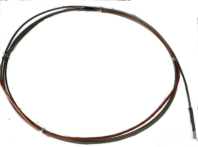
Fastron FRTD-6-3-750-2500 Resistance Temperature Detectors (RTD's)
Class A Accuracy
Teflon Screened Cable
Low Long Term Drift
Rated for -50 to 350 Deg C Max
Spring Cable Connection
2500 x 3mm (6 x 50mm Tip)
MIMS
Recommended to use BSP Fitting for mounting
Specification
Fastron Part Number
FRTD-6-3-2500-75
Sensor Type
RTD - Resistance Temperature Detectors
No of Wires
4
Shaft Length
2500mm
Shaft Thickness
3mm (6mm Tip)
Accuracy
Class A
Cable length
750mm
Cable Type
Teflon/Screened/Teflon
Temperature Range
-50 to 350 Deg C
Special Feature
6 x 50mm Tip
Mounting Style
BSP Bayonet or Flange Fitting Recommended
Weight
800g
Factory Pack Qty
1
Datasheet
ST6613 Rev 3
Fastron FRTD-6-250-500 Resistance Temperature Detectors (RTD's)
Class B Accuracy
Pt100 output
Teflon Screened Cable
Low Long Term Drift
Rated for -50 to 350 Deg C Max
250 x 6mm
MIMS
Recommended to use BSP Fitting for mounting
Specification
Fastron Part Number
FRTD-6-250-500
Sensor Type
RTD - Resistance Temperature Detectors
No of Wires
3
Shaft Length
250mm
Shaft Thickness
6mm
Accuracy
Class B
Cable length
500cm
Cable Type
Teflon/Teflon
Terminal Head Type
N/A
Maximum Temperature
-50 to 350 Deg C
Special Feature
N/A
Mounting Style
BSP Bayonet or Flange Fitting Recommended
Weight
300g
Factory Pack Qty
1
Datasheet
Datasheet