Fire Mode, Economical Firing Mode-Single Phase SCR Power Controller-Advanced Energy-Fastron Electronics Store")


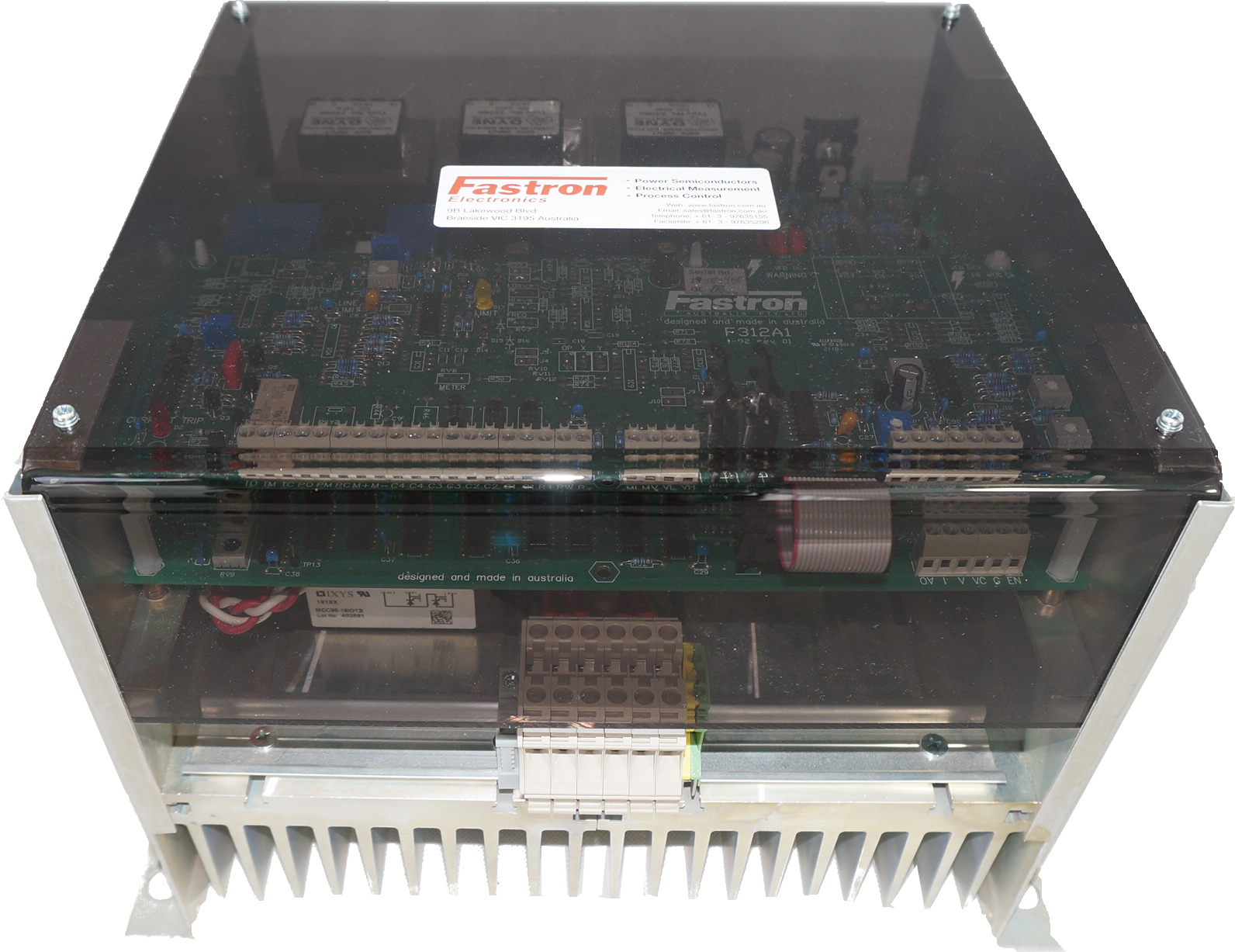
Installing Oztherm F330/F430/F431/F311 SCR Controllers
Full Controller User manuals can be downloaded here
The main points to consider:
1) Isolate and connect the incoming mains. We sure to use the correct Phase Rotation L1 (RED), L2 (White), L3 (Blue)
For 4 wire loads, a special -FW version needs to be specified at the time of order
For 3 wire loads connect L1,L2,L3 only
2) Connect Control input. Note default calibration if for 4-20mA. If other calibrated input is required you need to either specify at the time of order or see the calibration guide to recalibrate the controller for the desired input I.e. 10K POT or 0-10V/0-5V/2-10V/'0-20mA etc
3) Connect TS+/TS- if not already shorted. These are for NC thermal switch which gives thermal overload indication and will shut down the controller when it closes.
If thermal overload occurs you need to disconnect EN and G terminals and reconnect to rese the circuit
4) Connect any Current feedback CT's or Voltage Feedback transducers as per the control wiring diagrams here:
5) Apply the incoming power to the F330
6) Short terminals EN and G and apply control input signal, slowly increase until you get 100% output.
If you do not get full output and you do not have any feedback option then you will need to try the full calibration guide to recalibrate the control input.
If you do have feedback option such as C, CC, CE, CCE, or PW and you can not get the full voltage output then you may need to adjust the limit pot clockwise further in order to increase the feedback gain.
If the controller trips at start up then you may need to adjust the trip pot clockwise until it does not trip. If the controller still trips then they may be short in the system which could be heating element or SCR itself of faulty Controller PCB.
Once the controller is giving full output you can now adjust the limit and trip to where you want it to be. We normally supply the controller with limit set to 1/4 turn above the maximum setting and the trip pot 3/4 turns past the maximum.
Note: once the controller trips the EN and G needs to be removed and re-applied (or power can isolated and re-applied)
For further clarification please contact the friendly Fastron technical team
, DIN Rail Mount kWh Meter, Single Phase, 240VAC aux, Class 1, 100Amp Direct Connect, w/ 2 x pulse outputs and RS485 Modbus RTU Comms, MID Approved")