Fire Mode, Economical Firing Mode-Single Phase SCR Power Controller-Advanced Energy-Fastron Electronics Store")


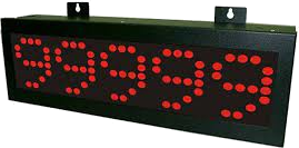
Setting up GMB Series Large Displays
In this Blog we discuss the important steps in setting up GMB Series Large Displays (or other Digital Displays by Alish)
Setting up Alish GMB Series Large Displays
Note: It is important to note that the settings shown in the user manuals provided are generally NOT the default settings. You need to take care to keep track of the dfalt settings or only adjust settings which you are familiar with.
1)Connect power, and 4-20mA Input as shown on the side label
2)Set the input to 4mA test signal.
3)To check settings press  until you see PID/0000 on screen
4)Press ENT several times until you see SYS
5)Press ENT to enter system settings mode.
6)Default settings (press ENT to scroll through)
Default settings in GBMA series (via supplied remote control)
DP = 0 -> This means there are no decimal points -> change as necessary by pressing ![]() keys
keys
DSL = 0 -> this means 4mA Input will Display 0 on screen (when calibrated correctly)
DSL = 2.5 -> this means 4mA Input will Display 2.5 on screen (when calibrated correctly, and decimal point was set to 2 above)
All other settings in SYS do not modify unless you need to change advanced settings. Default settings are generally fine.
ZB = 0000
ZDT = 0000
HB = 0000
HDT = 0000
SQR = NO -> square root math function
DIS = IP -> what parameter you wish to display (IP = input value)
FIL = 1 -> Input filter time constant
DOV = 99.99
AVG = 0010
LCU = 0000
COD = 0000 -> Set user password to access menu
LOC = NO -> To lock the settings
ID = 0000
Now the Display is set with default factory calibration.
If the Display is showing an offset, such as with 4mA is showing 0.02 etc on screen then check the calibration and wiring to the input connections of the GBMA display meter first .
Otherwise you can try fine adjusting the the scaling. If both low and high scaling limits show the same offset then you can try to modify the AOF setting form in ADJ menu from the default. For example if the offset is 0.02 so you see 4mA = 0.02 and 20mA = 2.52 then you can set AOF to -2 to correct this.
However if you are seeing only 4mA = 0.02 and 20mA = 2.5o then you should adjust the DSL number down by 0.02 to -0.02 to correct this. If there are still some random movement then you can consider increasing the Filter time constant value (FIL) to above 1, the higher the number the more filtering and the longer the display will take to change values
The default settings for ADJ menu are as follows.
DOF = 00.00
DGA = 1.000
AOF = 0000
AGA = 0000
For other models such as GBMT
The settings are the same, the main difference is the input range. For example GMMT-K is for Type K thermocouple Input -200 to 1360 Deg C
Note: -200 Deg C will be the DSL, and +1360 will be the DSH default setting. By default he until will display the actual temperature the probe read so there should be no need to adjustment
For further advice feel free to contact out friendly sales team at Fastron Electronics
To see our range if Digital Panel Meters online see our online store
, DIN Rail Mount kWh Meter, Single Phase, 240VAC aux, Class 1, 100Amp Direct Connect, w/ 2 x pulse outputs and RS485 Modbus RTU Comms, MID Approved")